PROJECT 3

Comparison of two identical containers
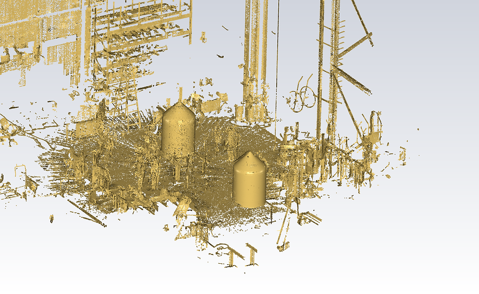
Comparison of two identical containers: Point cloud of both containers

Comparison of both containers with representation of the deviation from each other
Comparison of two identical containers
Component analysis of two identical tanks
Based on a design drawing two identical tanks were recorded using 3D laser scanning (accuracy 5/10mm) and then dimensionally checked to see whether an agitator installed later had sufficient distance to the inside wall of the tank.
The container geometry shows a curvature in the transition between the cylinder and the cone lid.
The evaluation is particularly problematic in this area, since no mathematically comprehensible body can be defined. The point cloud was sliced wafer-thin at the level of the evaluation level and a millimeter-sized best-fit cylinder was determined.
The sections show that the permitted deviations are exceeded in individual parts, and reworking of the container wall is necessary.